J. P. Dilo- CEO of DiloGroup, [email protected], Im Hohenend 11, 69412 Eberbach, Germany
For three-dimensional fibre structures Additive textile manufacturing in nonwovens
Abstract
Within the optiformTEX research project, a new textile web-forming technology was developed in order to position fibre mass according to a programmed 3D topology, which is defined by the mechanical requirements for moulding as well as for strength and acoustical properties.
The variation of fibre mass in the space of 3D structures also depends on the application within the car. This project will be concluded in 2020 and will provide a solid tool for the optimum manufacturing of lightweight fibrous structures for moulded interior components.
As a result, savings in fibre mass of up to ca. 20 % are achievable. The textile process from fibre opening through aerodynamic web forming by airlay units will direct fibre mass in varying amounts to different locations in the web’s plane.
This new and special nonwoven textile technology will be explained in detail in order to shed light on prerequisites, production rates and tolerances of quality features with respect to the mass distribution in optimized topological structures.
1. Introduction
The largest cost factor in textile production is fibre material costs. A good reason, therefore, to always look into fibre consumption when producing a technical textile that should function as a component to resist force by its strength and stiffness, to dampen noise and to insulate from extreme temperatures.
Part of the physical parameters needed for this functional structure can be provided by the fibre mass at the proper location, where it is needed as a supply of physical properties. Fibre savings have an additional effect when moulded parts for the interior of cars or aircrafts are applied. Less mass in cars and planes reduces the fuel or energy consumption directly.
Therefore, it has been an objective to develop a nonwovens process which allocates fibre mass on the plain of a nonwoven support sheet used as a sub-structure and forms a 3D topology of added fibre with varying mass, thickness, strength, stiffness and insulation capacity. Already in 2012, DILO applied for patents describing a device and process to apply an array of single “aerodynamic web forming units” across the production width which can control the amount of fibre released in MD and CD direction.
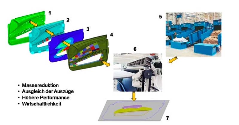
These DILO patents describe the technical ingredients of such a solution which has met similar activities in 2016 by the technical university of Chemnitz and a consortium of partners to pursue this route of development. In the meantime this project is soon to be concluded and the DILO “3D-Lofter” is a solution which fulfils the objectives to form 3D fibre structures.
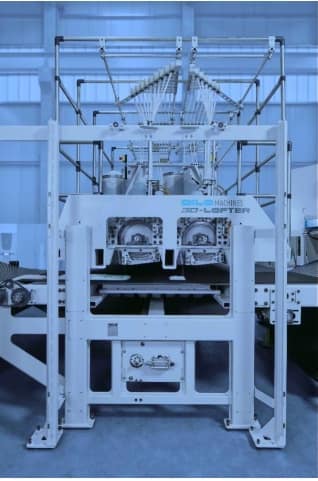
2. The functions of the 3D-Lofter machine and process

Step 1 is the supply of fibre in an adequate form which can easily be opened and dispersed in a stream of air. In addition, the supply of fibre should be precisely dosed as defined in varying mass over time. Three different possibilities have been described:
1. Feed of fibre flocks
2. Feed of pre-needled strands of felt 3. Feed of sliver
3. Feed of sliver
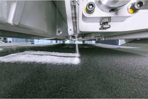
The latter two offer very precise dosing capabilities by a precise distribution of fibre mass over length. Sliver is an easy source for fibre mass of any type of material out of staple fibre with any fineness, staple length, crimp, finish, etc.; also in a mixed form as e.g. polyester in combination with carbon in order to achieve particular strength and stiffness properties.
The sliver is drawn into the opener of the airlay unit between the infeed roller and a feed plate, underneath or overhead. The feed roll is driven by a variable speed drive controlled by a program. The infeed rollers are segmented and individually driven in front of a high-speed opening roll which stretches across the whole width of the machine.
A stream of air is used to detach the fibre from the opening roller more easily and place it onto the pre-needled substrate over a screen apron which is air-permeable and uses suction underneath in order to support the web-formation. Several of those side by side web-forming heads may be used in a series of web-forming stations in running direction.
After web-formation the material with its three-dimensional fibre distribution is needled in a classical needleloom, yet preferably with the “Hyperpunch” feature, the elliptical needling mode. Before the conversion into a moulded part, referencing of the local coordinates is necessary for a subsequent dye-cutting, deep-moulding and thermo-fusion process.
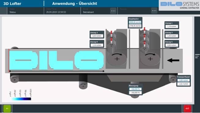
Programming the right amount of fibre mass at the right location is easily carried out directly at the controls of the machine or online with data stemming from an FEM analysis of the moulded finished part in order to allocate and match fibre amount with topological properties. This altogether has been investigated within the optiformTEX team and should concluded tentatively during 2020.
3. Technological parameters
So far, our tests have shown that a mass per unit area of the base material of up to ca. 1,000 g/m2 is not hindering the aerodynamic web-formation on top of it. The mass added may vary up to 800 g/m2, all certainly depending on fibre parameters like fineness and others. So far, the working width is 500 mm. Since the design is modular, we can add more units in order to enlarge it.
A width of ca. 2.50 m is envisaged. The thickness of the air laid material was up to ca. 100 mm, a throughput speed while web- forming and subsequent needling of 8 m/min. has been attained. Any fibre material may be used from natural fibres to man-made organic or mineral fibre, including glass and carbon.
Anything which can be spun as a material would be available as a sliver in a can. The sliver material can be varied across the width and along the MD direction. Therefore, a huge variety of topological 3D structures out of fibre are imaginable to form parts finely adapted to performance criteria.
4. Physical Properties of 3D formed fibre structures
The following test methods have been applied in order to analyse the physical properties:
Measurements of weight, thickness and strength. The tensile test also is an indicator of the stiffness of the material in machine and cross direction, if we look into the initial modulus of force over elongation. At the same time, this is an indicator of the fibre orientation in the material.
A comparison of property values of the substrate only and the 3D “additives” gives insight into the potential of adding topological properties.
5. Areas of application
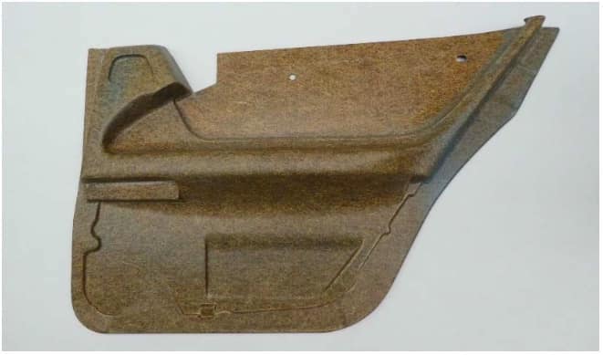
As mentioned earlier, the products of the “3D-Lofter” process seem to be ideal for the car interior. The deep-moulding of flat sheets of needle-punched material creates areas during the pressing and drawing which have a high concentration of strain and stress.
After the deep-drawing process there should not be thin areas in the moulded part, which are lacking a minimum thickness and strength or have cracked completely. Those points can be identified by FEM analysis of the flow of material in order to receive a guideline where to place additional material which adds the required fibre mass at the right place, e.g. of strain concentration.
Areas of potential interest could be, besides the car interior, mattress and upholstery applications and could include the garment and shoe sector whenever a varying thickness for cushioning, supporting and protecting is intended. Furthermore, technical textiles for filtration or geo-synthetic applications as well as composite structures could call for adding varying fibre mass at spots of high strain and stress concentration where the addition of fibre mass would reduce such concentration, particularly at points of load introduction. By the same token, the 3D-Lofter could work as a colour patterning tool for needle felted floor coverings.
6. Economics
There is a high potential for the reduction of fibre mass, costs and weight in the car when 3D topological parts are manufactured according to the functional needs. According to a study of TU Chemnitz the potential for fibre mass savings lies in an area of 20-30 % of the complete part’s fibre mass. In order to illustrate this we would assume that a flat sheet of needled material has to have an overall thickness according to the maximum of thickness needed at a load introduction point.
With reference to the work of TU Chemnitz some examples of automotive interior parts have been analysed with the result that the maximum of fibre savings at a real automotive part was ca. 28 %. The total weight of the part was 370 g, the lightweight structure in comparison had only 270 g. These are theoretical investigations; nevertheless, due to the finely segmented structure, a close proximity to real values may be assumed.
Of course, competitive methods to add fibre mass at critical areas could be robotic pick-and-place methods, for example. The 3D-Lofter process, however, is a tool for mass production at a considerable rate of speed. Therefore, I assume that the continuous web-forming and needling process has a good chance to match high expectations for short cycle times.
7. IsoFeed
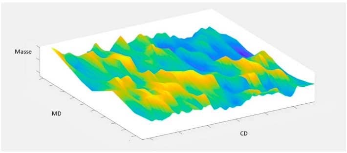
A further application of individual web-forming heads is the area of fibre feeding to cards and airlay units. In nonwoven lines, in many cases card/crosslapper combinations are used, while the card is fed by a flock mat. A flock mat has got a rather uneven mass structure. This unevenness ranges up to ca.12 % CV.
This irregular fibre mass flow to the card causes irregularities in the produced web. Particularly when running cards without crosslapper directly in front of a thermo-bonding calender or water- entanglement line, the evenness of the web is crucial to the final quality of a nonwoven.

Years of development have made card feeders produce more regularity in their flock mats. However, a certain minimum of around 5 % CV is hard to lower further. Therefore, the additive method of applying additional fibre mass at “void” areas with lower weight can raise the overall regularity of flock mats theoretically by around 40 % and consequently the web uniformity after the card or the evenness of an aero-dynamically formed fleece could be enhanced, resulting in a much better quality of web-forming and better visual quality of the nonwoven product.
Fibre savings would be considerable in case a minimum weight at a certain spot had been defined which should stay above a lower average mass per unit area. Less mass variation allows to reduce the average.
Therefore, the “IsoFeed” process of filling “void” spots in order to improve the regularity of the mass distribution is an “inverse” process to the 3D topology of forming irregular structures.
8. Resume
The “3D-Lofter” is a machine and a part of a process to provide all the means of producing light-weight fibre structures according to the functional and physical needs in applications as car interior parts, along with a high potential of fibre and cost savings.
So far, nonwoven manufacturing processes, be it card/crosslapper combinations, direct cards or aero-dynamic web-forming, were capable to only produce relatively even flat structures of the same areal weight or thickness. The new “3D-Lofter” technology gives a high resolution of individually formed webs with a high degree of programmed variation of fibre mass.


